The copper, solved for its near field.
A schematic and its board are two files in code. The near-field and cross-section solvers read the board as drawn and show where its switching current couples into its sensor lines.
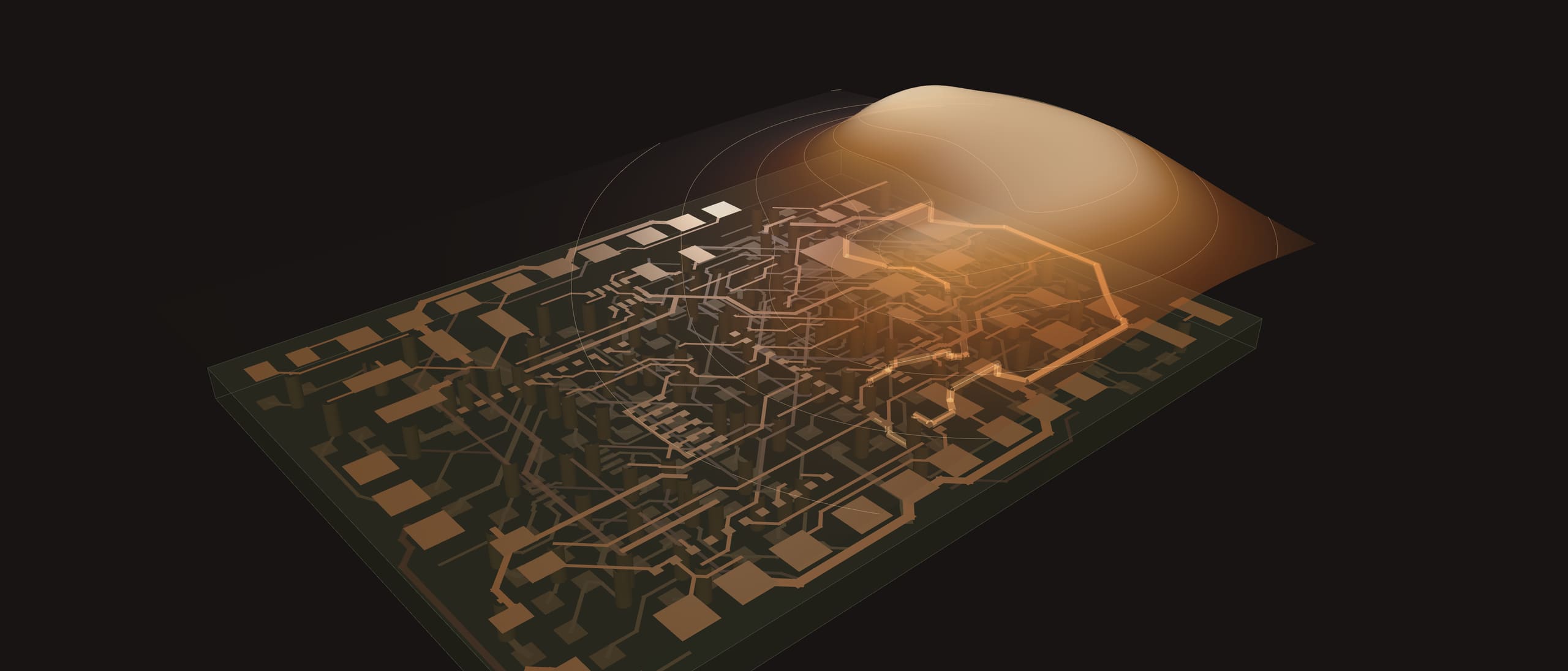
Case study · UpperBody-001's Hand board
84 A/m over the coil, 0.7 kA/m on the touch lines.
The hand's 6 V servo regulator switches about 1.07 A of ripple through its output loop. The near-field solver sums that current's field over the board's copper. A probe plane 3 mm over the top face reads its peak above the coil, L1. The touch-sensor lines run under the loop on an inner layer, and the field there is more than eight times stronger.
- at most on the probe plane, 3 mm over L1
- 84 A/m
- at most along ELE10, on the inner layer under the loop
- 724 A/m
- peak to peak of ripple, from the board's L1 and rails at an assumed 500 kHz
- 1.07 A
Simulated
hardware/modules/UpperBody-001/ee/Hand board.pcb.tsxOutput case-studies/boards-and-fields/media/hand-board.emi.jsonTool scripts/sites/emi-study.mts (board-emi.ts: near-field.ts, cross-section.ts)Ran on This computer (dell-gb10-1)When The cut through the board
More than half of ELE9's capacitance is to the switch node.
Where the switch node crosses the touch lines, the cross-section solver cuts the board and solves the electric field between 14 conductors. The touch electrode ELE9 has 97 pF/m in all, and 55 pF/m of it is to the switch node, so each switching edge reaches its reading.
The board's file names no layer stack, so the study assumed a 4-layer 1.6 mm one (JLC04161H-7628). Every assumption is in the study's file.
Simulated
- of ELE9 is to the switch node
- 55 of 97 pF/m
- conductors in the cut, solved in 1,357 iterations
- 14
- schematics and 9 boards in code across our products (
case-studies/boards-and-fields/stats.json) - 20
hardware/modules/UpperBody-001/ee/Hand board.pcb.tsxOutput case-studies/boards-and-fields/media/hand-board.emi.jsonTool scripts/sites/emi-study.mts (cross-section.ts)Ran on This computer (dell-gb10-1)When Find the coupling before the board is made.
Write the board in code, run the near field and the cut on it, move a trace, and run them again.