Toolpaths from the part, held to the machine.
The feeds come from the tool, the material and the machine's ceilings. A flat outline is planned here in milliseconds; a solid goes to FreeCAD's Path.
Case study 1 · the speed and the feed
The spindle is the limit, so the feed follows it.
UpperBody-001's lamp plate is 92 × 46 × 3 mm of aluminium. The fleet's 3018 routers carry a 180 W spindle. Its kit page gives 7,000 rpm at 24 V, which no unit has measured. Aluminium wants a faster spindle, so the feeds engine ran it at that ceiling and worked the feed out from it, keeping the chip load.
The engine also said what a machinist would: a full-width slot has nowhere for its chips to go, so take a lighter depth than a profile pass, or cut it trochoidally.
- , held at the machine's ceiling
- 7,000 rpm
- feed for a 3.175 mm two-flute end mill
- 370 mm/min
- chip per tooth
- 0.026 mm
- of cutting power, of the spindle's 180 W
- 4.7 W
cloud://home/user-commandagi/case-studies/cam/lamp-plate-feeds.call.jsonRun runs/20261104t163340z-lamp-plate-feedsTool fab_feedsRan on This computer (dell-gb10-1)When Case study 2 · the outline and the holes
Ten passes, four tabs to hold the part.
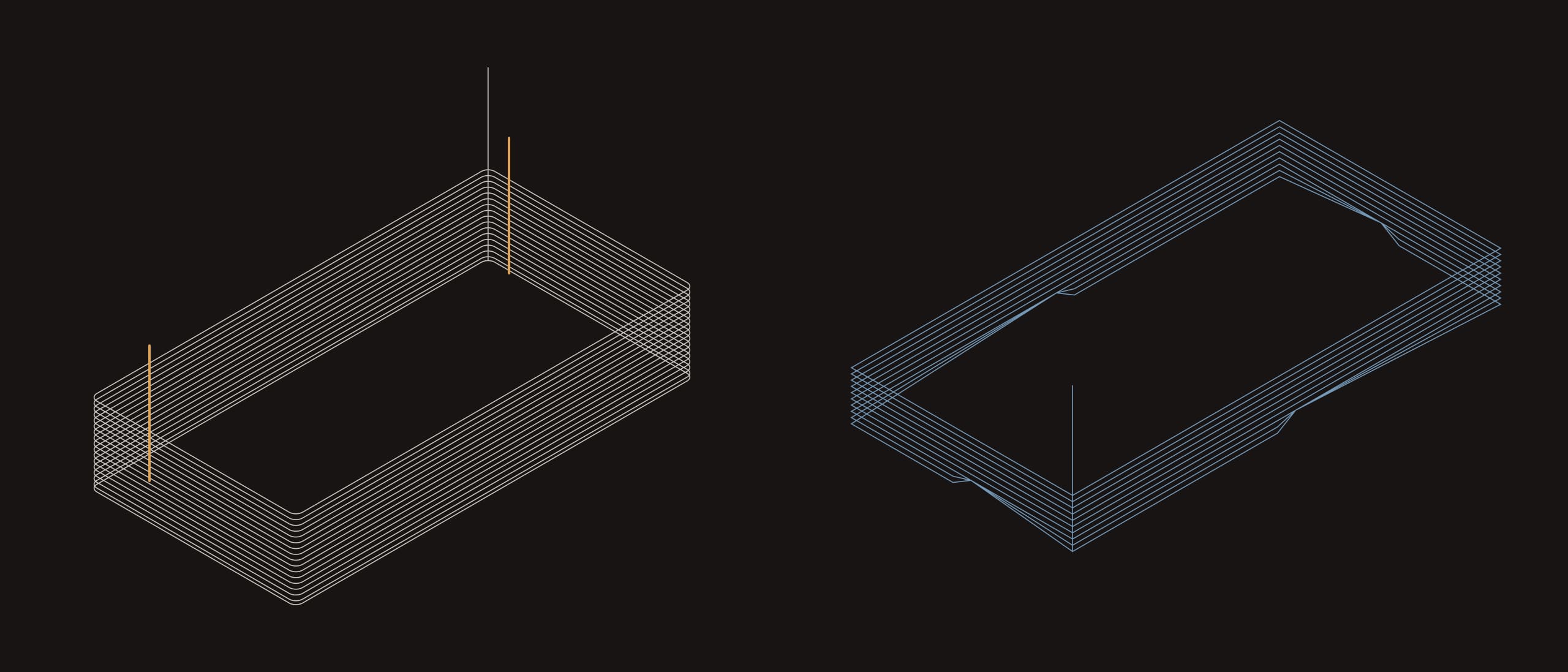
On the right, fab_mill_region cut the outline free in 0.3 mm passes and left four tabs, so the plate does not come loose into the cutter on the last pass. On the left, FreeCAD's Path contoured and drilled the same plate from the module's own solid in Body.3d.tsx. The picture draws the depth four times its size.
- passes through 3 mm
- 10
- of cut, about 7.8 min at 370 mm/min
- 2,887 mm
- tabs, holding 16 mm of the outline
- 4
- holes of Ø3.4, pecked 0.5 mm at a time
- 2
cloud://home/user-commandagi/case-studies/cam/lamp-plate-profile.call.jsonRun runs/20261104t163342z-lamp-plate-profileTool fab_mill_region; fab_cam (FreeCAD Path)Ran on This computer (dell-gb10-1)When What the machine would get
Two programs for grbl, unvalidated until a part is cut.
The contour and the drilling are each one program, posted for the grbl controller of the 3018 and held to its 300 × 180 × 45 mm travel. Every program says unvalidated: no part has been cut with it on a real machine, and sending it to one is a separate, granted act.
- lines in the contour program
- 201
- lines in the drilling program
- 123
- travel each program was held to
- 300 × 180 × 45 mm
- of the fleet's routers commissioned
- 0
cloud://home/user-commandagi/case-studies/cam/lamp-plate-contour.call.jsonRun runs/20261104t163324z-lamp-plate-contourTool fab_cam: FreeCAD Path in cam-eval, grbl postRan on This computer (dell-gb10-1)When Plan a cut on your machine.
Name the tool, the stock and the machine. An agent plans the path and says when a number would break a tool.